2015-05-17
#breakout board v0.3
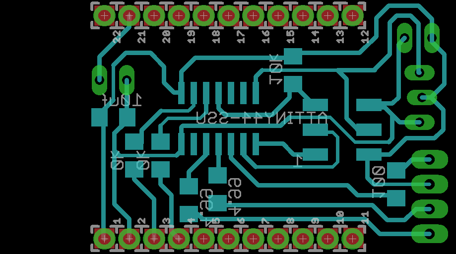
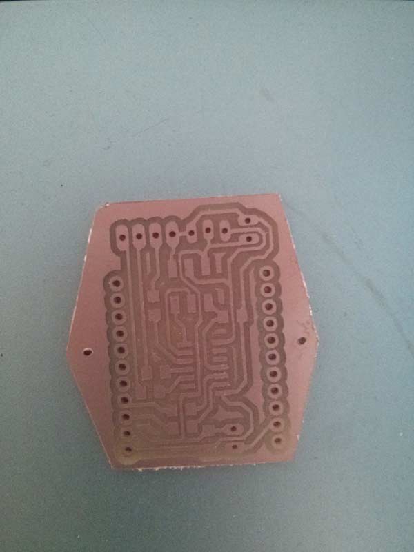
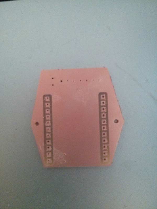
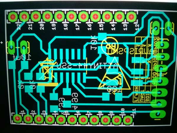
Finally, with the changes I had in mind from the 0.2 version, I can now present the final board I am going to use for the final project.
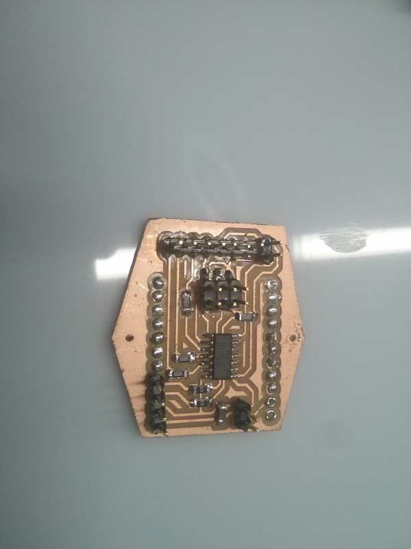
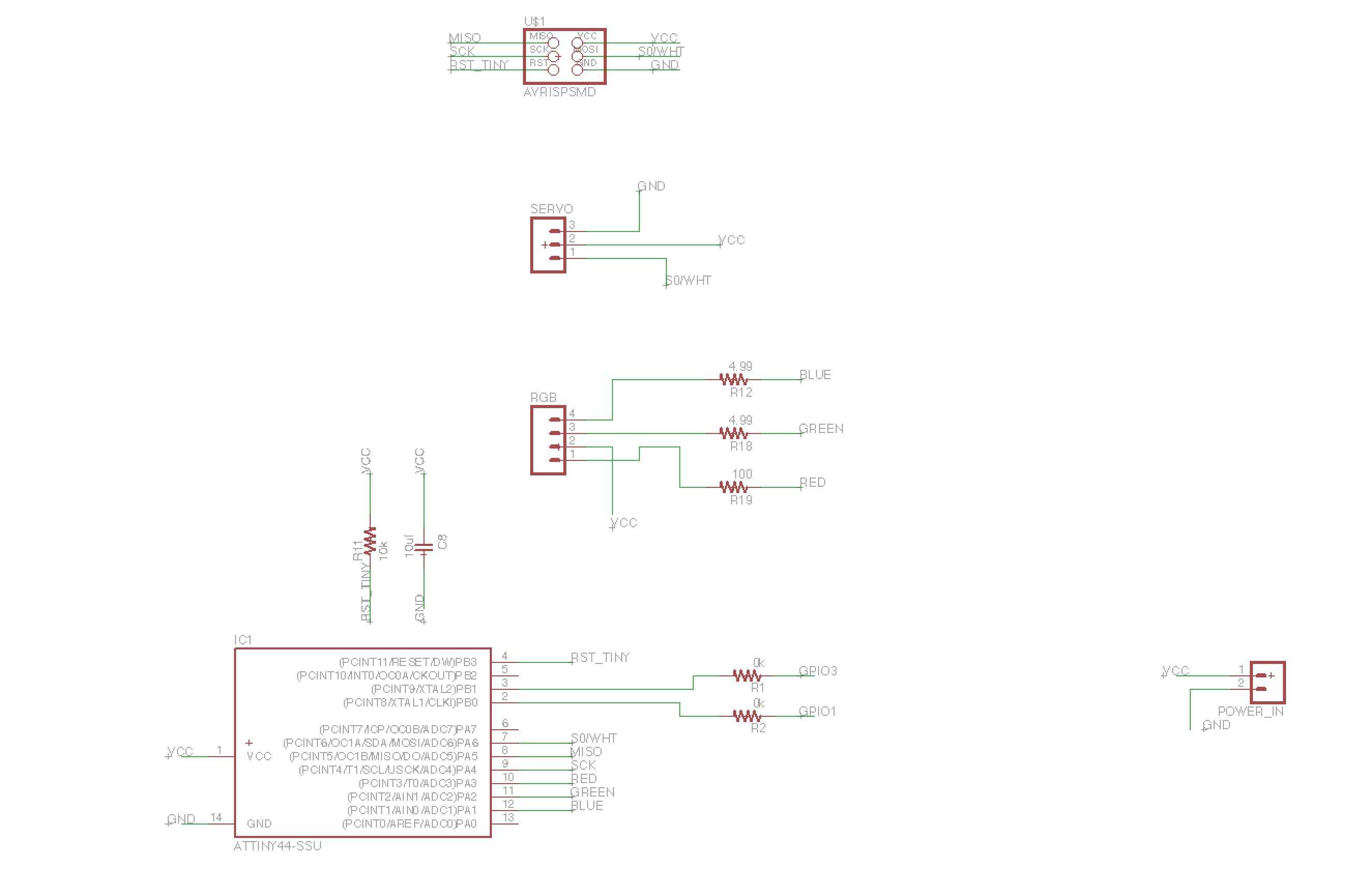
Component List:
- 2x 0k resistor
- 2x 4.99ohm resistor
- 1x 100ohm resistor
- 1x 10k resistor
- 1x 10uf capacitor
-
1x attiny44
- 3x2 JP connector
- 4x1 JP connector
- 3x1 JP connector
-
2x 2x1 JP connector
2015-05-10
#breakout board v0.2
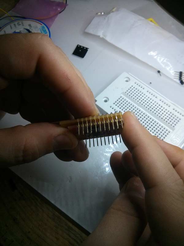
In the 0.2 version I wanted to use a double face and double layer board, trying to correct some mistakes of the previous version and taking the regulator off, since I tried to power all the device with a 3.7v battery.
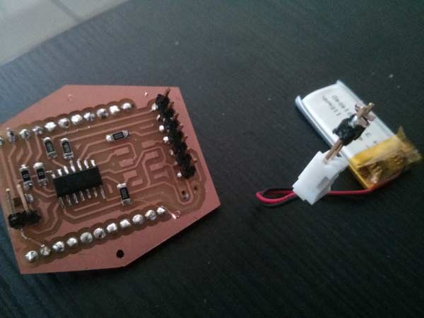
Unfortunately, as you can deduce from the picture on the right, I still have some trouble with the battery connector: since I used the male Jp pins available in the FabLab either than the specific ones for the battery. After using the battery a few times, the connector on the breakout board side, unplugged. In this board version the ground and voltage cable of the servo motor were inverted, as well as the voltage and green pins of the led RGB connector.
##Battery test
Even if I made a few mistakes, I managed to do some tests with a 3.7v / 200mA minibattery. Both the servo and the led didn’t have any issues in powering and checking the full battery voltage with the tester I always found a value around 3.63v max, coherent with the Esp 8266 datasheet.
2015-04-29
#breakout board v0.1
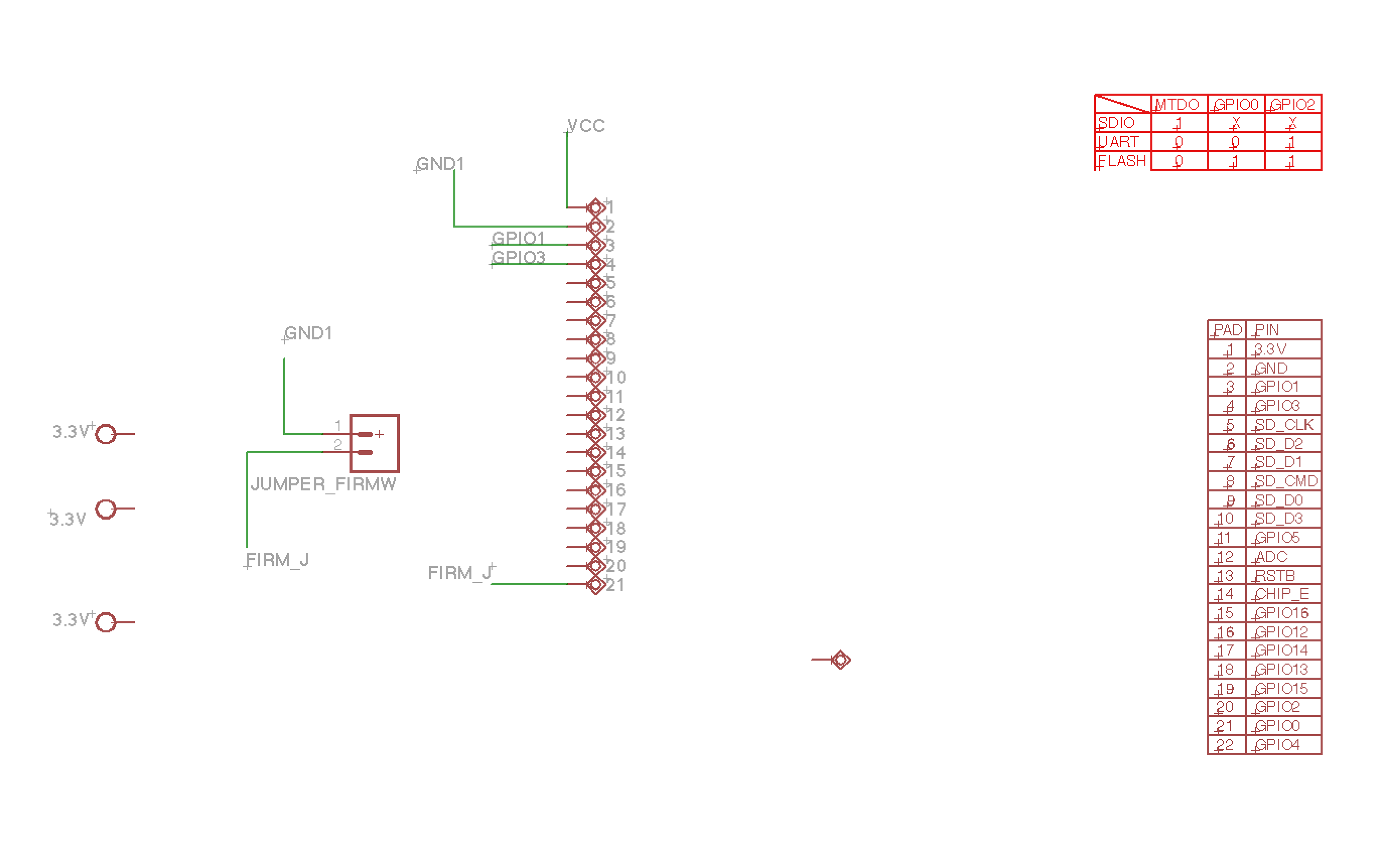
After many reserching on Internet, I decided to try the new board without voltage regulator, because, carefully reading the datasheet of the Esp8266, I realized that it is able to work with a maximum voltage of 3.6v and variable absorptions (min 0.5 uA / max 215 mA).
The first board I created from the shematich downloaded from the DEV esp8266 revA website.
2015-04-25
LM3480 is to be replaced by LM3940 1-A ! I wrong the linear voltage regulator in RGB 3.3v Servo 5v board ! After discover that ESP 01 was insufficent to do what I want…I need to redisign my breakout board for integrate the ESP8266 rev A by Olimex, add a Button (maybe direct from Gpio pin of the WiFi board)
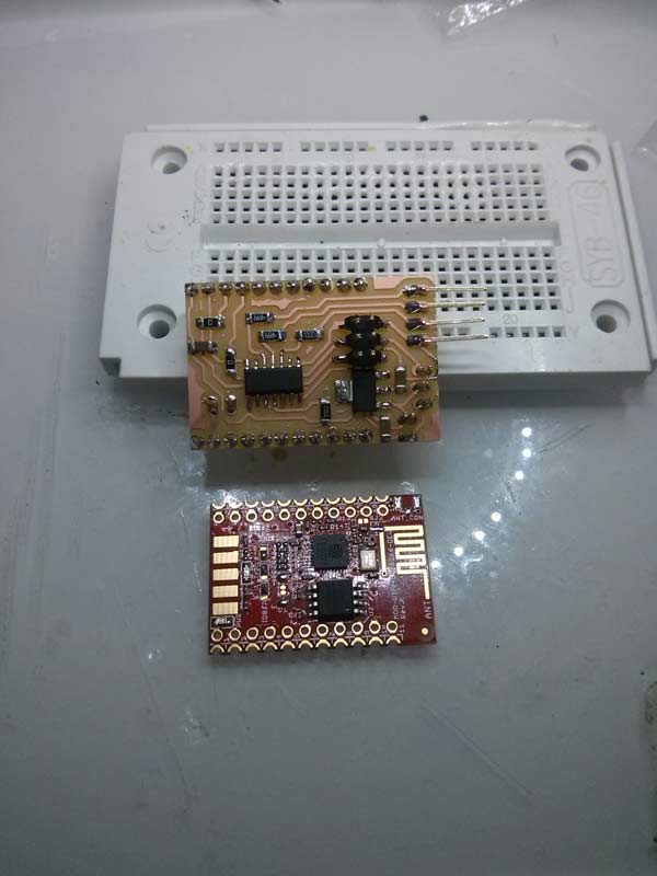
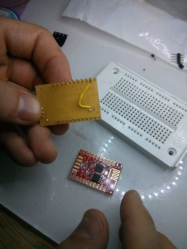
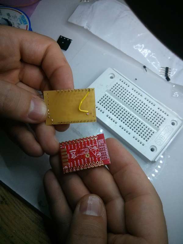
2015-04-21
output device: I created a similar breakout pcb board, to interface ESP with ATTYNY44.
-
I had to undestand better the battery features and the mini servo for insert a proper voltage regulator (by now I used a LM3480).
2015-03-11
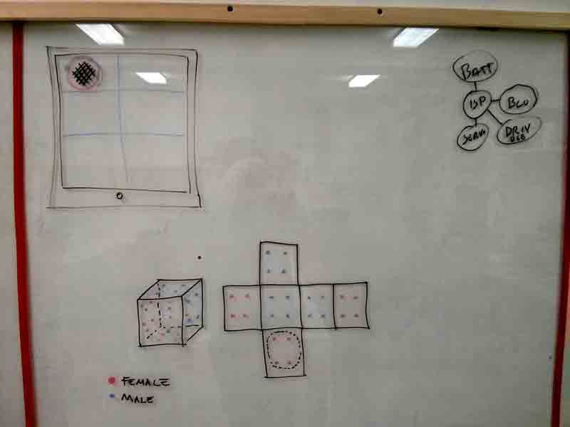
Schematic plan:
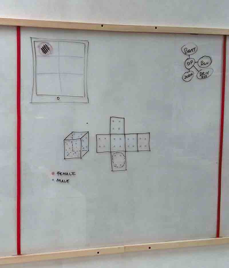
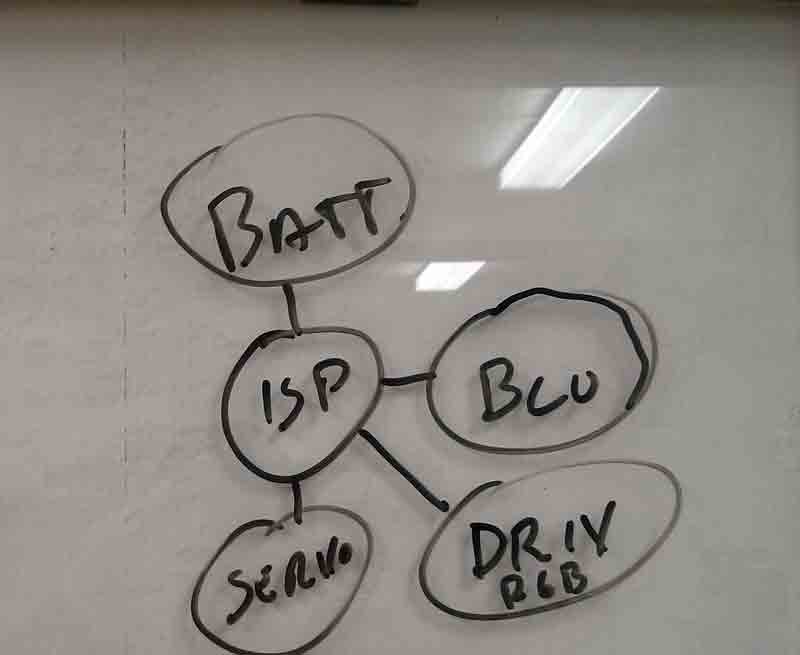
Batt = Battery
isp = microcontroller
Servo
Blu = wireless connection
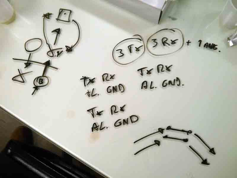
maybe I need 6 free pin ??
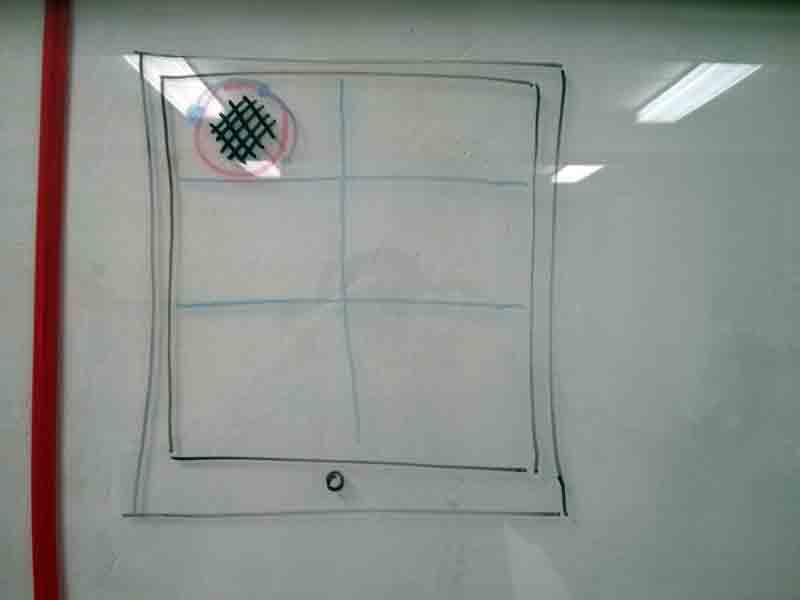
tablet/computer APP
Arrow to turn the cube.
Tap inside the circle for change cube color.
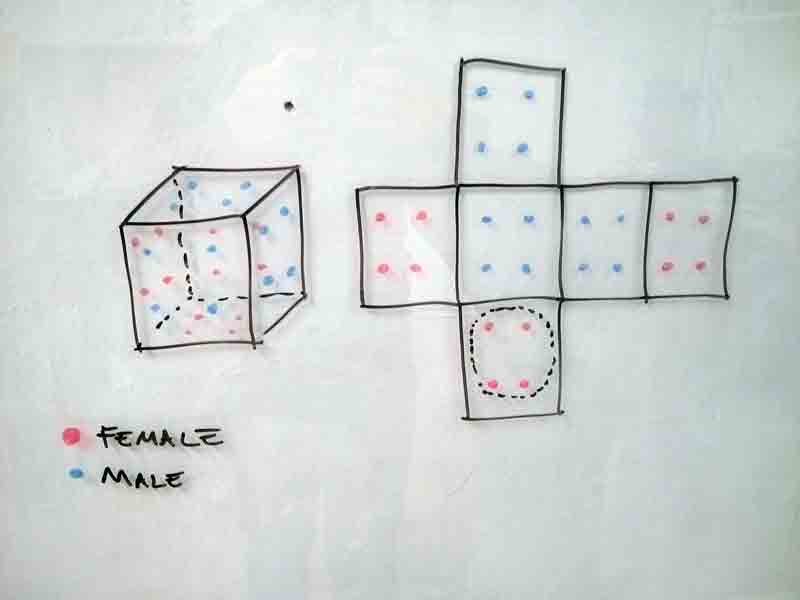
how the Cube can connect each other.