Weekly_Assignments :
- Redraw the echo hello-world board
- add (at least) a button and LED (with current-limiting resistor)
  check the design rules, and make it
- extra credit: simulate its operation
#####What I have used:
- ######Eletronics Design : Eagle Freeware
- ######Roland MDX-20
- ######Soldering Station
- ######Hello Board + led + switch:
Design! in Eagle
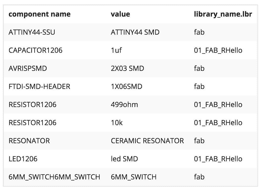
I was totally new to eagle. that is a very easy program For creating board such as hello board I simply have to load the necessary libraries, in this case I used the library FAB, 01_fab_Rhello and one suggested by our instructor SparkFun in this video tutorial
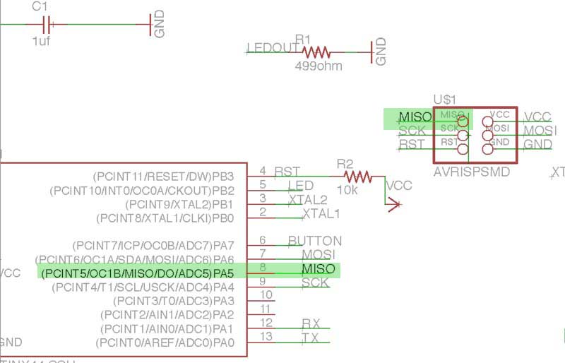
Once I have created a new project, I can start adding some components.(as indicated in the table above) In Eagle you have 3 foundamental windows:
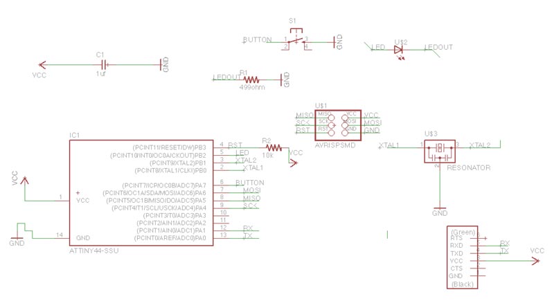
- schematic where you can visualize and add components.
- board where you can move and build traces , design study of your new board.
- control panel where it is possible to activate and add libraries
in schematic window, there are 2 methods to create connection between components:
- linking them directly using a net
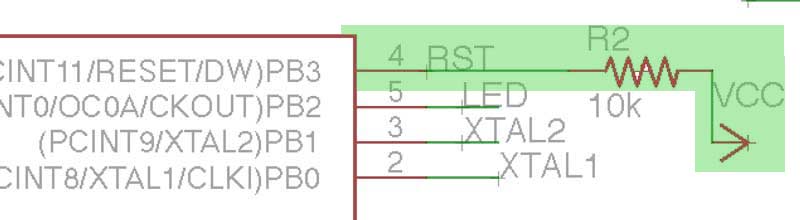
- or naming the extremes with the same name
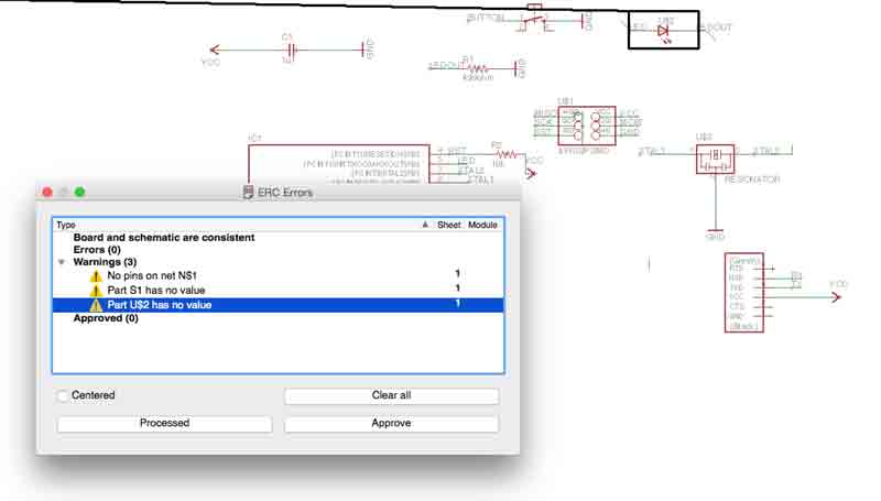
Tools—>ERC performs a check on the connections to be corrected
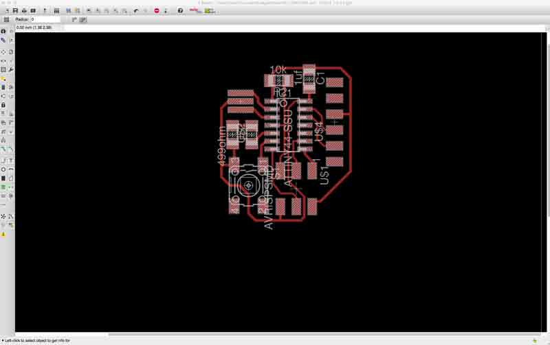
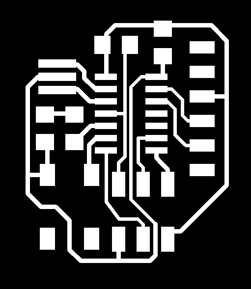
Now I’m ready to draw the card and its physical connections in the window Board.
To draw the card I had to change the settings of the grid because the standard setting was too big. view—>grid
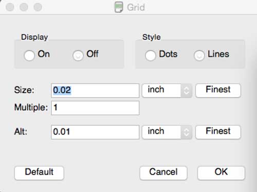
I try to place the components the nearest possible to have a very smaller board. For the traces inside (under) the Attiny44 I had to change the traces dimension
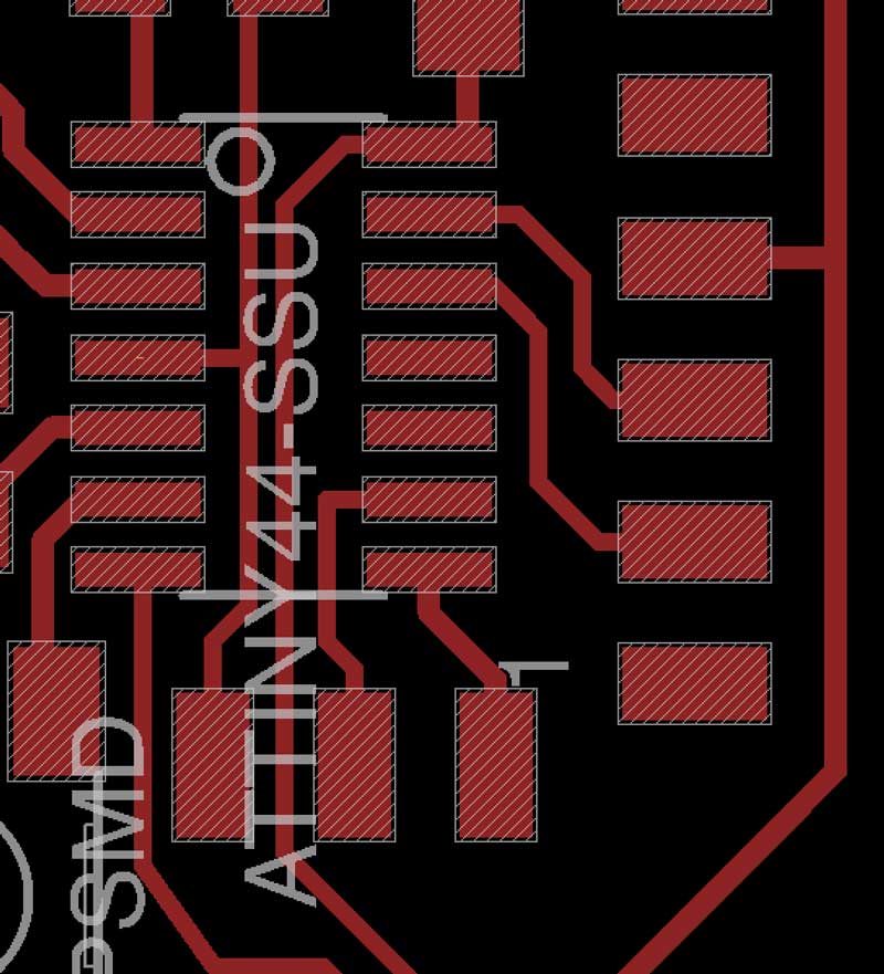
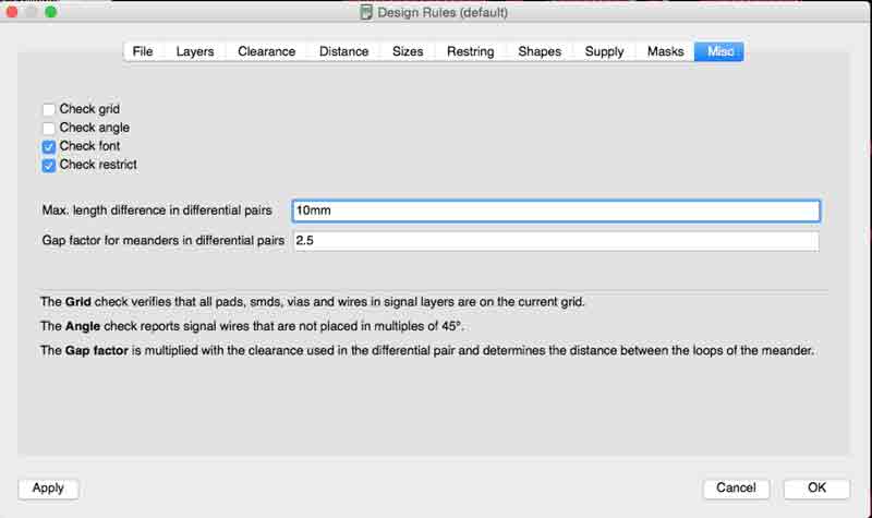
then I had to check the minimum distance between the tracks with:
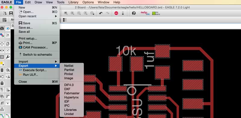
file—>export—>image with this setting:
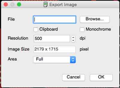
I Opened the file with photoshop .png, cropped the outline of the board with a little edge. I Created a new layer with white contour outlines of the same dimension of the crop. here you are the two files I created:

ATTENTION In order to import the file in .png—>fab modules you have to set 500 dpi, (such as in the export on eagle) otherwise you will mill a board of 20 cm! (default DPi in Fab modules are 72).
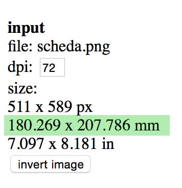
When I tried to mill a giant 20cm board, the mdx-20 went straight to the extreme of X axes and started milling from that point ! fortunately I was near the machine and I was able to stop Mdx-20 just in time before the tip touched the copper board.
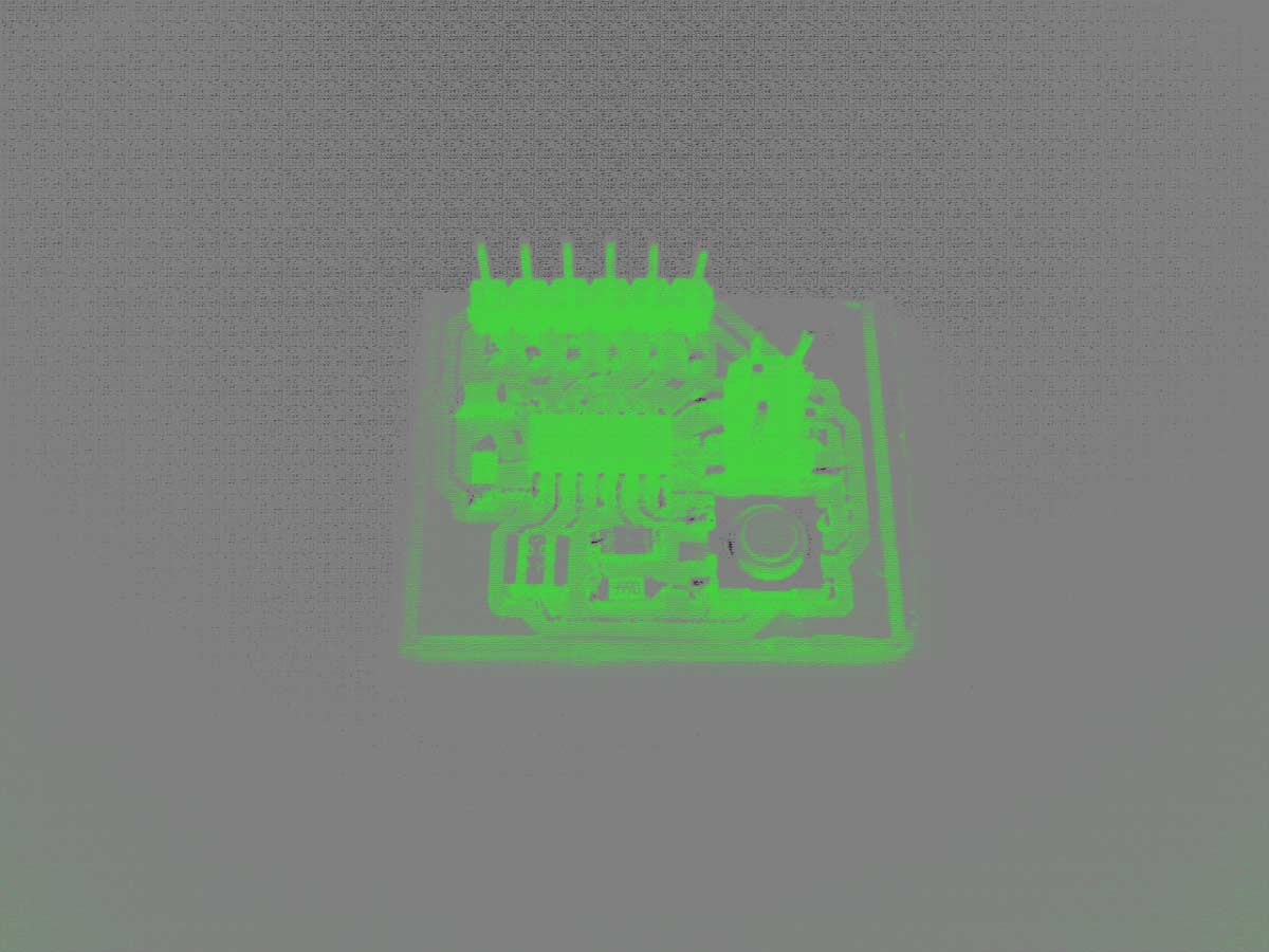
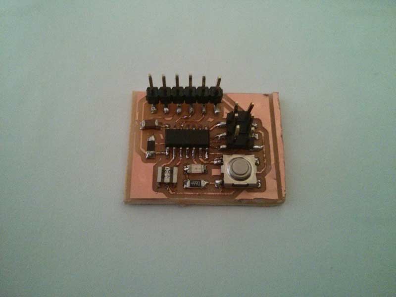
Final Result hello board with led and switch