Weekly_Assignments :
-  make a machine, including the end effector build the passive parts and operate it manually + automate your machine
    (document your individual contribution)
#####Useful (inspiration) links:
#####What I have used:
- ######Solidworks
Introduction
We wanted to create a four-axis motion machine, able to create wax rings. I have been looking around the web for some infos in order to build such machine, specially focusing on machines doing the same work or having the same kind of axis motion. In the process for the building of this machine - we’re going to call it M2M-ring - I have tried to experiment a completely parametric design. Basically, I have reduced as much as possible the parameters for the size of the machine, actually increasing the number of functions to declare the proportions and the measurements of the machine.
Dimension, Function and Equation
With this assignment I wanted to test the chance to create a machine that is completely settable with commands from the section dedicated to variables on SOlidWorks. So, I created 14 variables:
- H = machine height (external case)
- L = machine lenght (external case)
- *nema internal = distance between the holes of the motor block
- nema external = external motor measurement
- bars = diameter of smooth bars
- trehead rods = diameter of the trehead rods of the motor
- hole_nema = holes to fix the the motor block
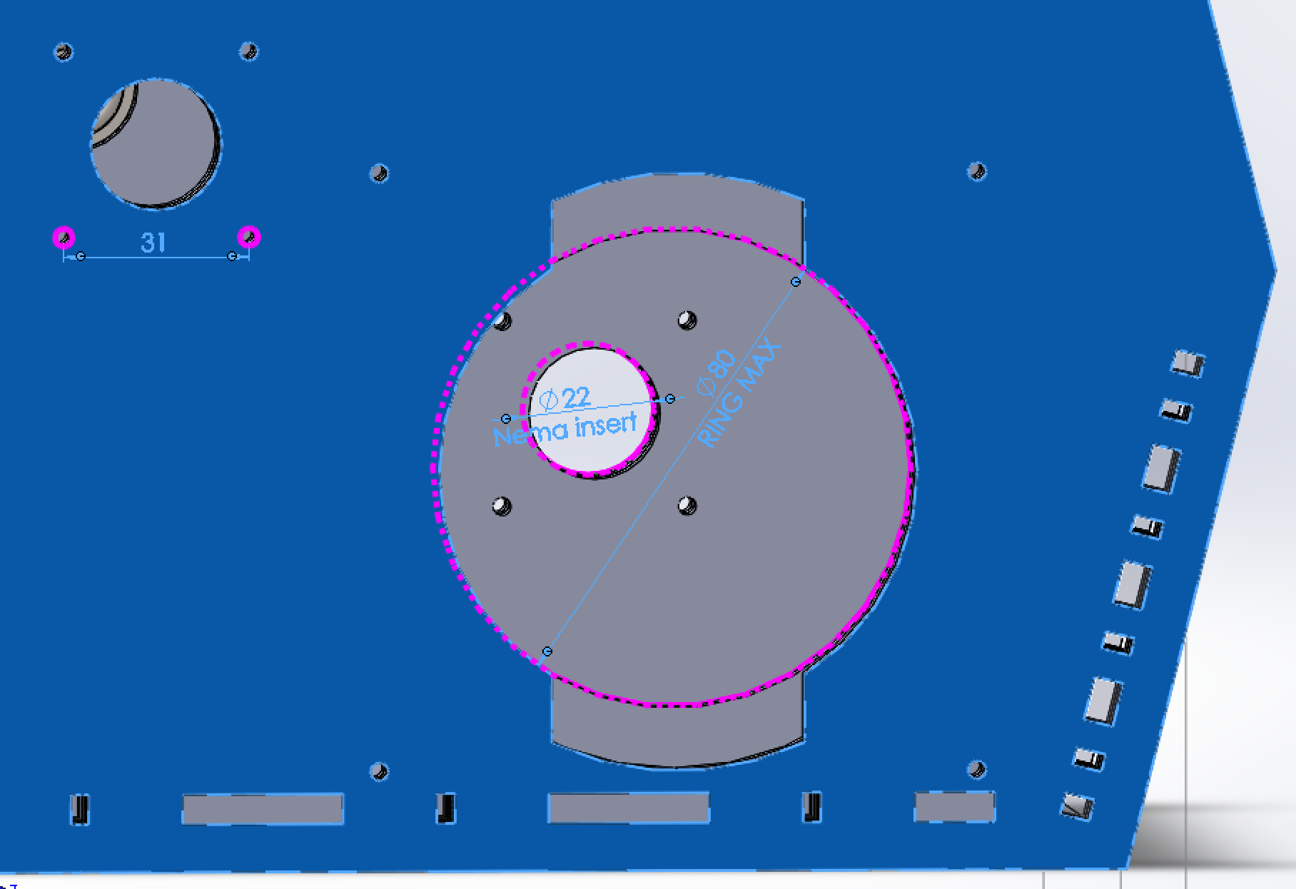
- ring dimension MAX = maximal dimension for milling the ring
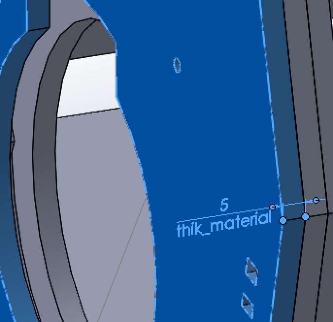
- thik material = thickness of the material used in the construction of the machine
- kerf = parmeter for cutting (only available in specific circumstances, in this project)
- ring_b = diameter needed to fix the point of the rotation of the rotating axis without letting it shifting aside (to be developped)
- motor_rods = diameter of the hole where the treheaded rods of the motors will pass (trehead_rods+0.3)
- nema_insert = diameter of the joint of the nema motors
- zz809 = external diamter of the zz809 bearings
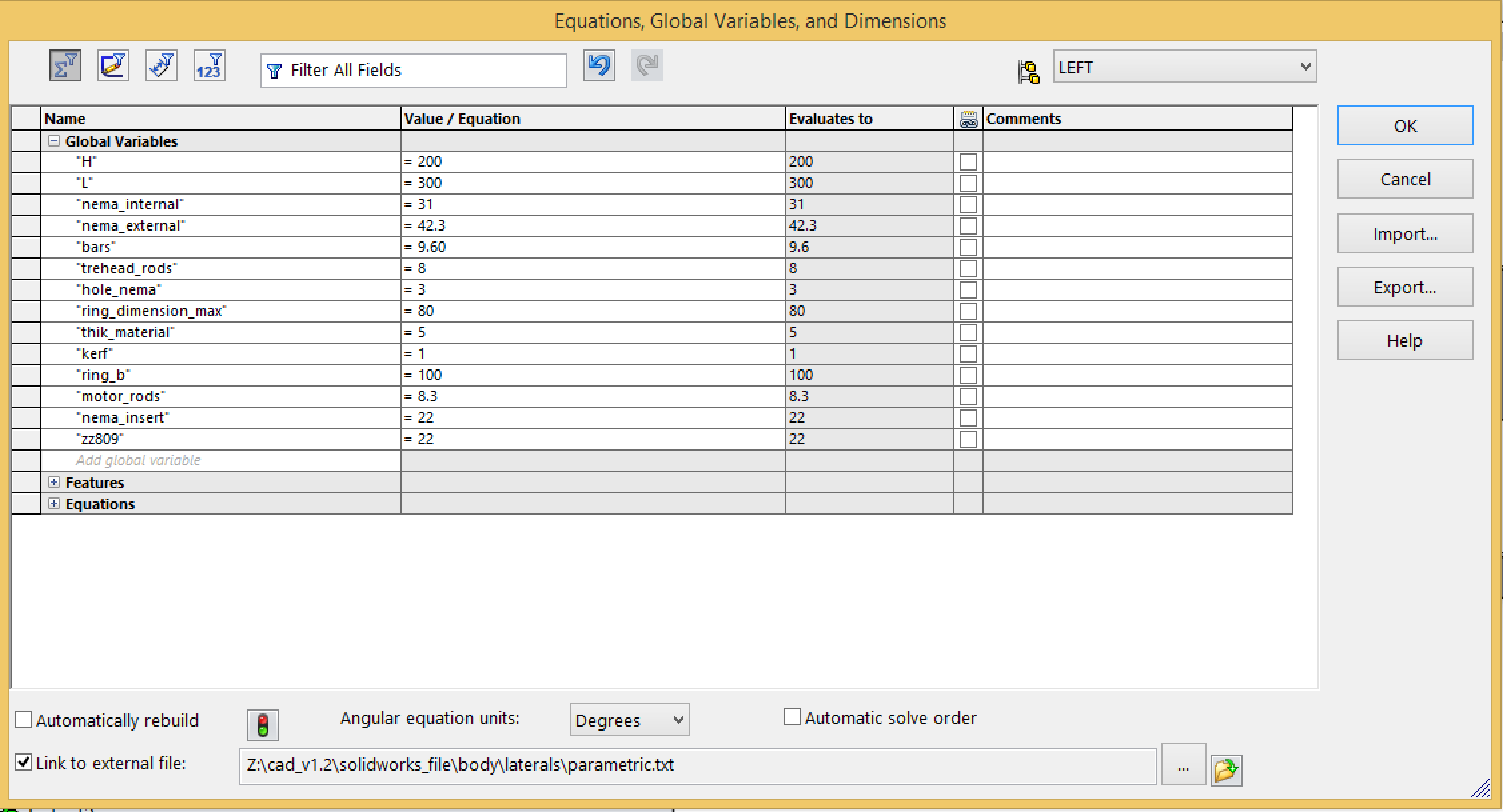
In the section dedicated to variables on the software you can find all the correspondences between the applied variables and the designed project in every single sketch. i
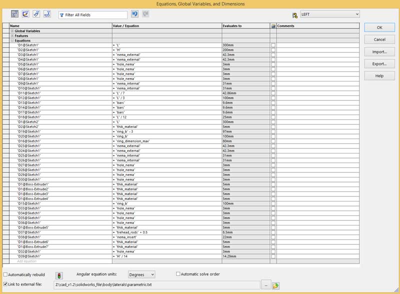
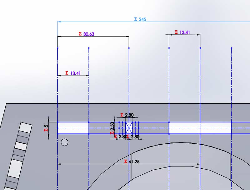
In the following picture, a sample of how I used the equations without inserting any value to create the autosetting joints for the external case.

#Design
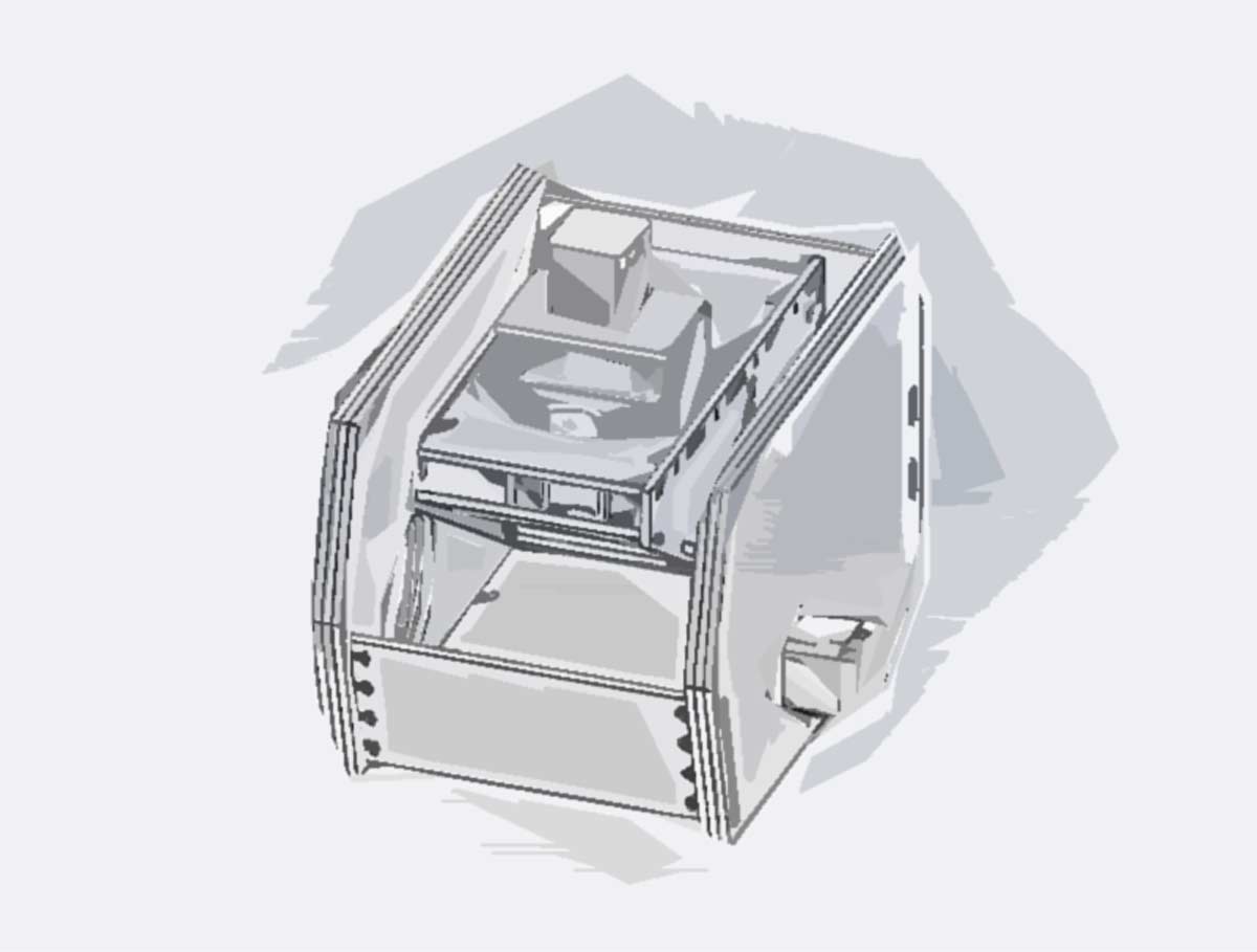
I started the design with some sketches on paper, to understand the maximal size of the working area: it being a machine to mill machinable wax we have to think about a few centimeters motion per each axis.
The machine is made of 3 layers on each side, building the lateral walls. The 3 layers increase the stability of the machine and give it the possibility to create internal joints, for bearings or counterjamb for axis and bars.
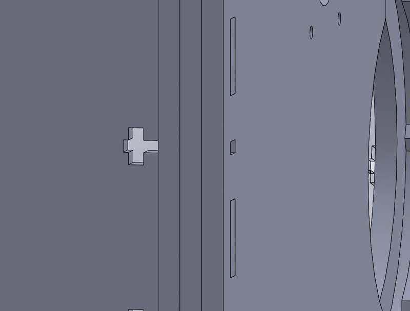
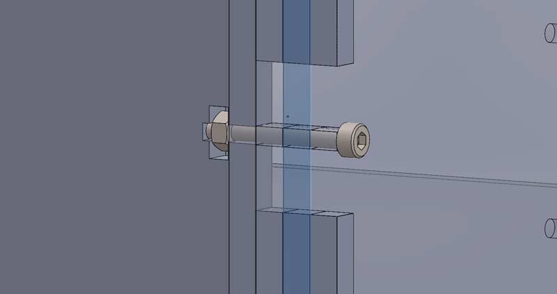
For the external case, I developped a kind of joint able to hold both the simple wood joint and a M3-20 screw with a nut, in order to guarantee a major stability.
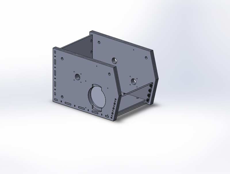
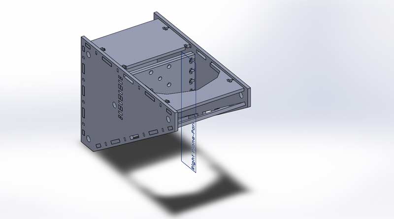
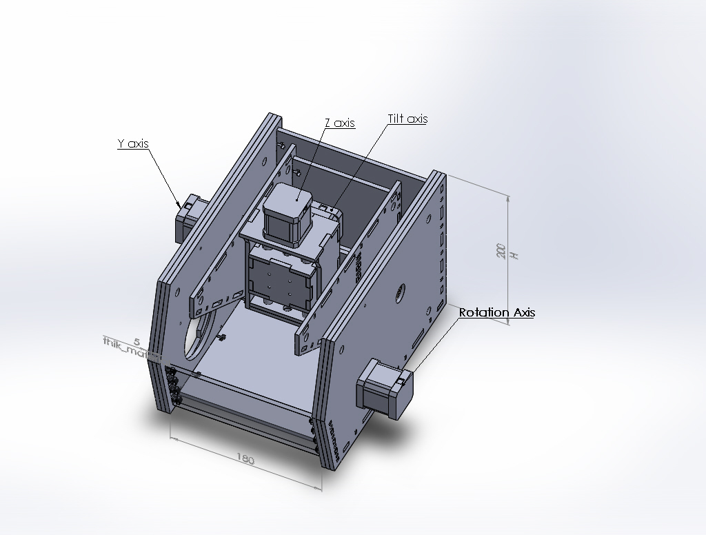
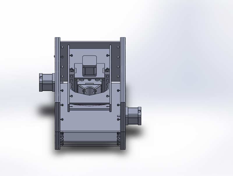
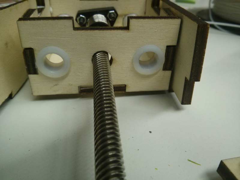
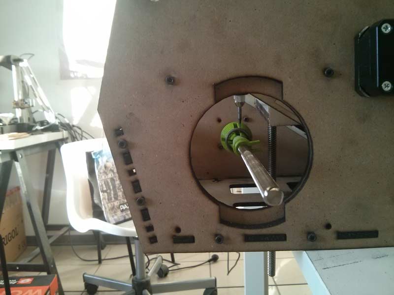
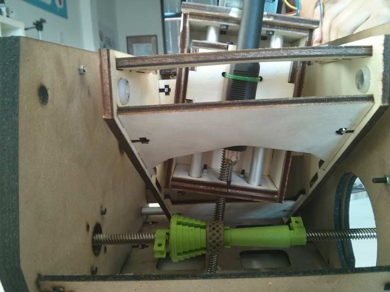
Completed external case. One of the walls has a bigger hole, in order to let the rough part inside the machine. The rough part will than be blocked with a special 3d printed part. In an upcoming phase, we will develop a joint system with a central bearing through this shaped hole that will avoid the lower shifting of the bar (due to the mandrel working). The maximum work area is the blue rectangle.
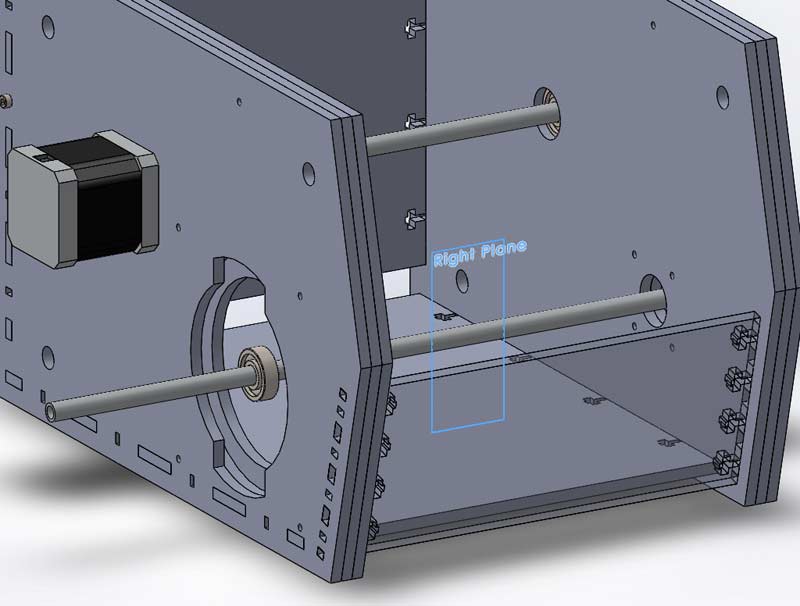
The upper motor is used for the Y motion, while the lower motor is dedicated to the rotation of the object.
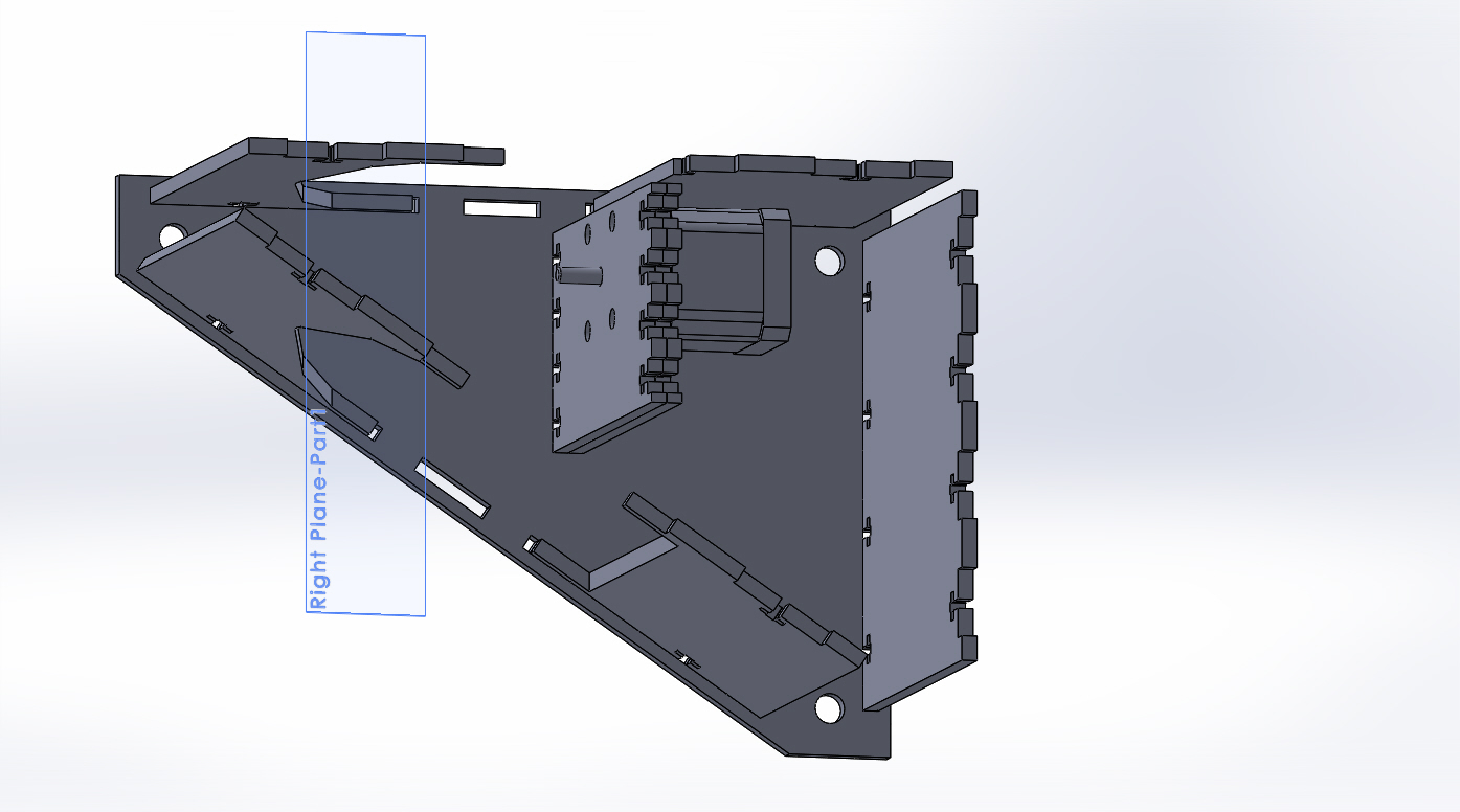
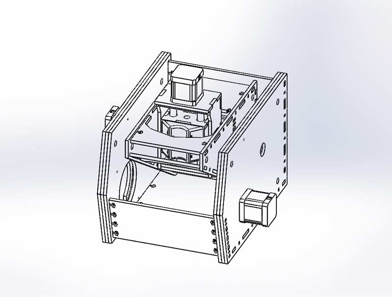
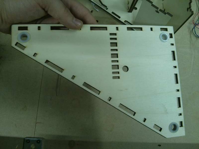
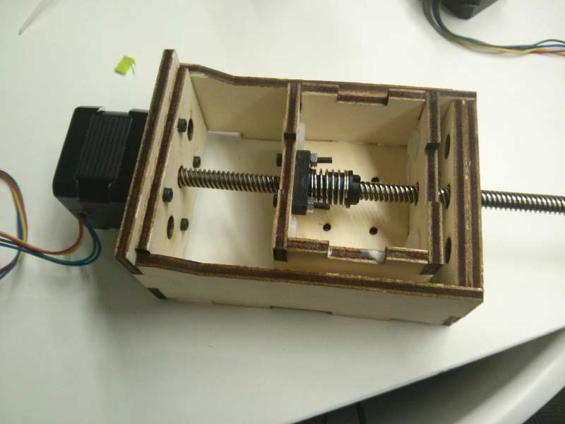
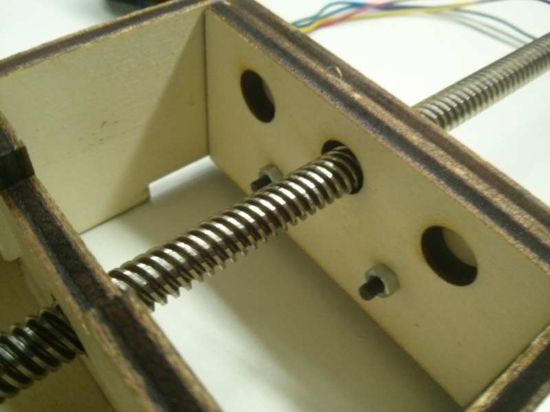
This trinagle is the Y axis and it has been built around the work area (blue rectangle in the picture). It has 3 points for shifting of smooth bars, while the endless screw of the nema 17 that allows the Y axis movement.
Inside the Y axis, the nema 17 allows the tilt of the mandrel that is fixed with screws to the 2 internal walls. (Be careful: the screws get into the first wall and connect to the second one via the nema 17, in order to allow the tilt movement ont he first wall.
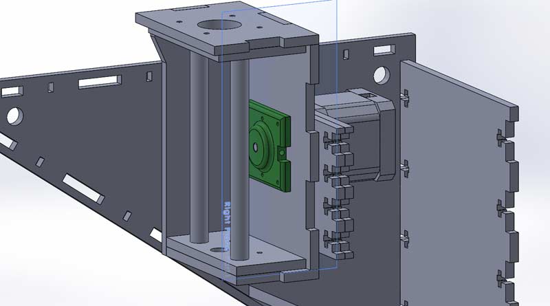
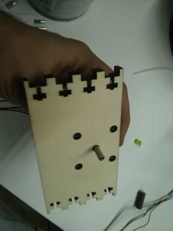
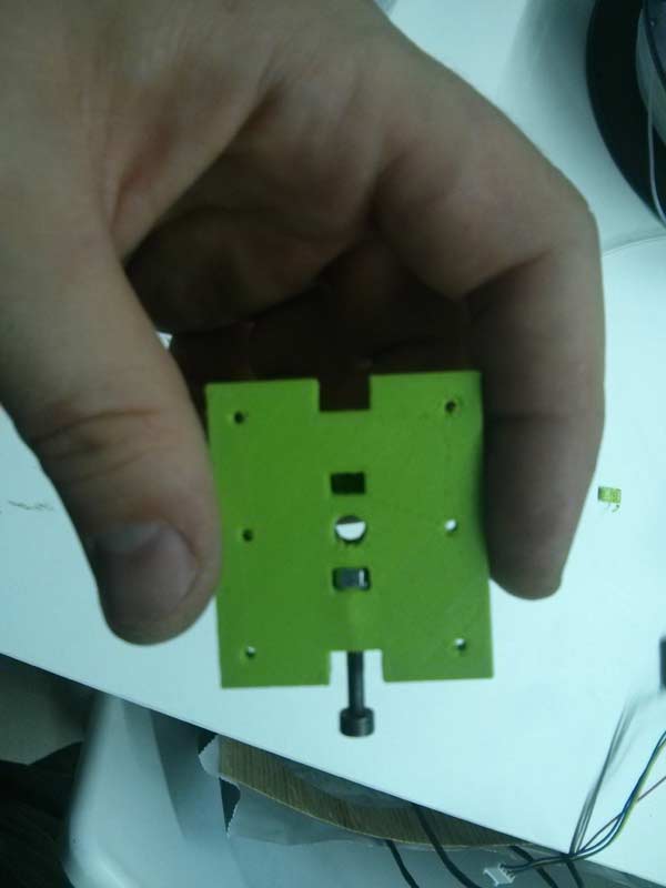
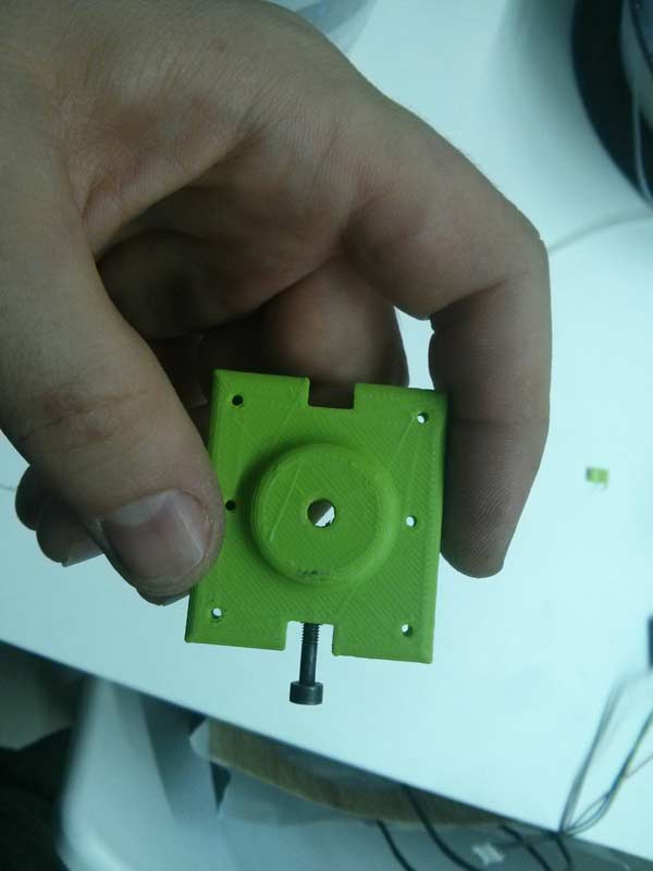
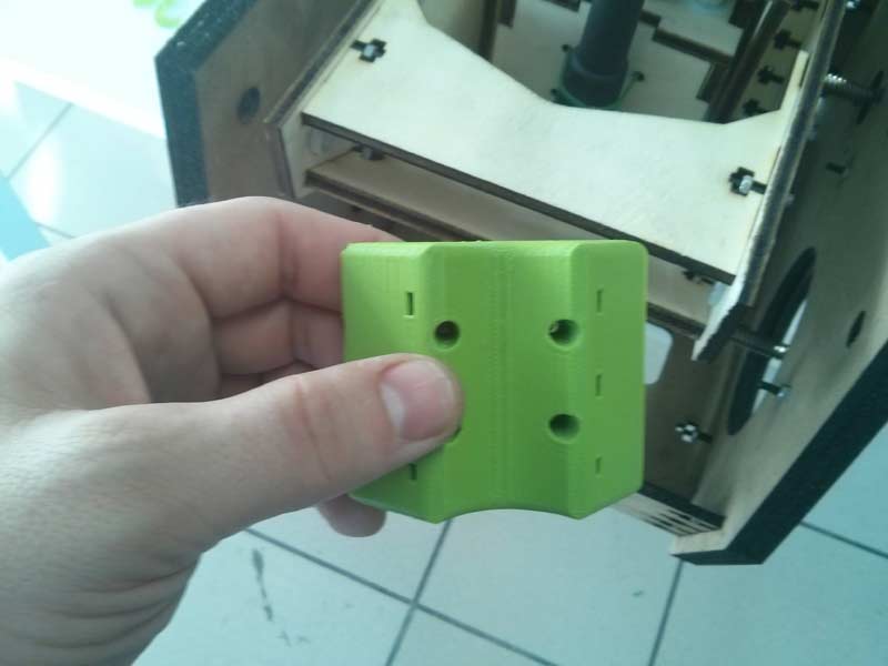
The component on which the Z axis will slide is now inserted. It is fixed on the nema 17 only with the special 3d printed element (in green).
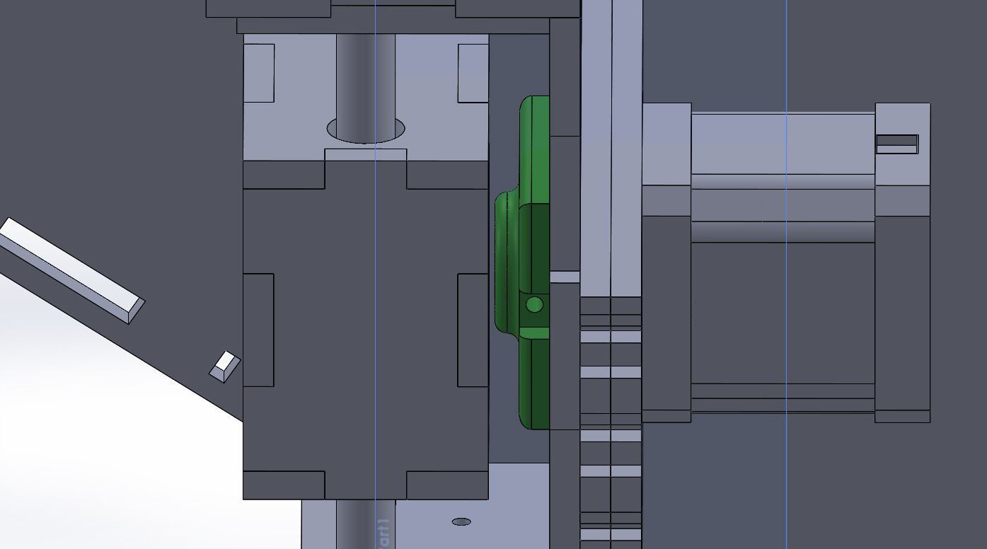
Interference area between the 3d printed part allowing the tilt and the element sliding on the bars of the Z axis motion.
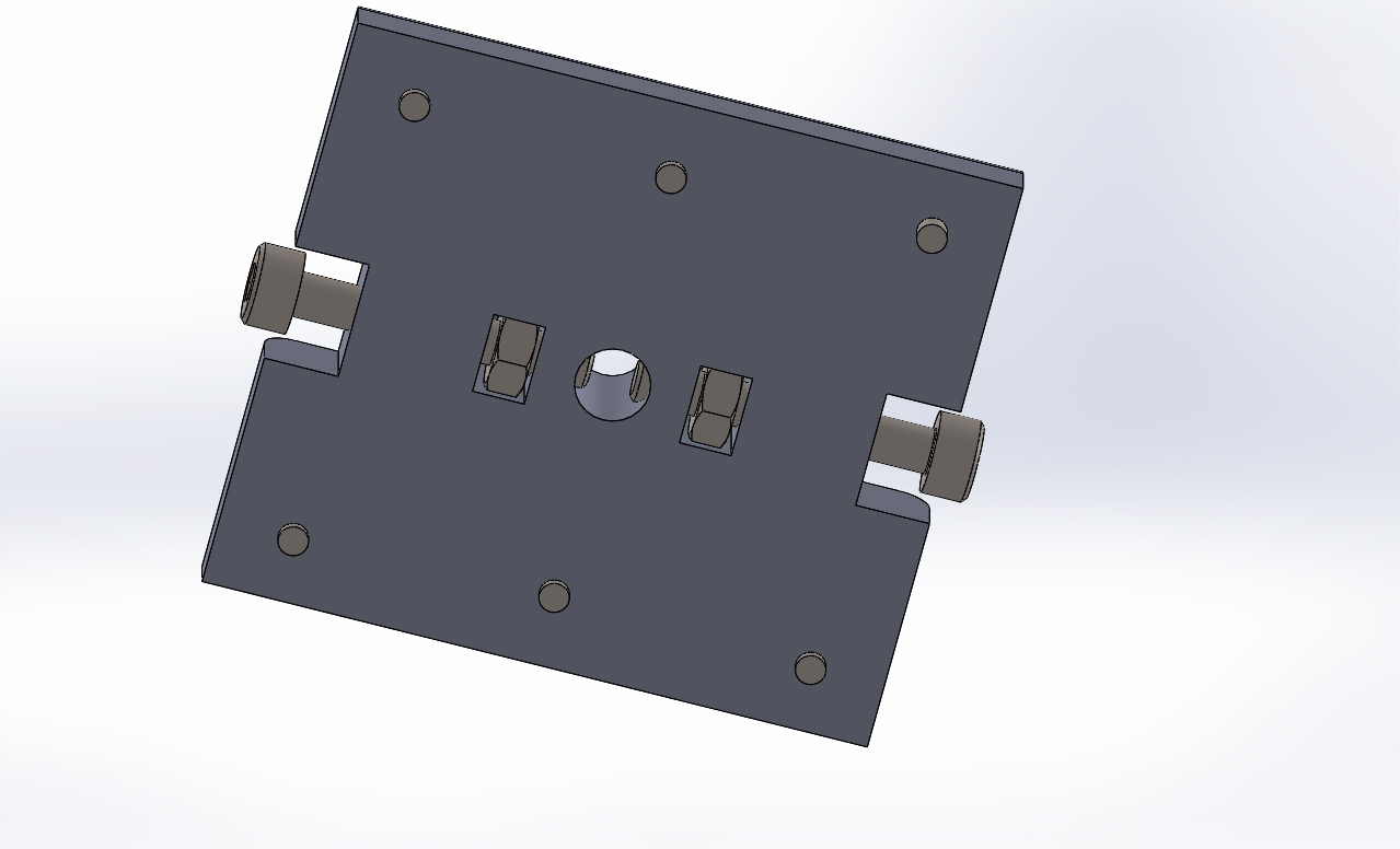
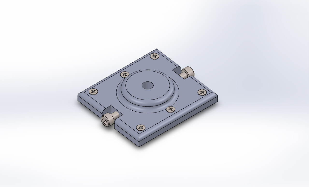
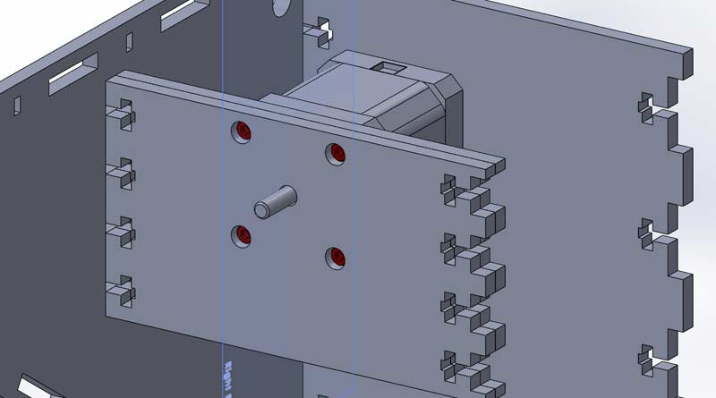
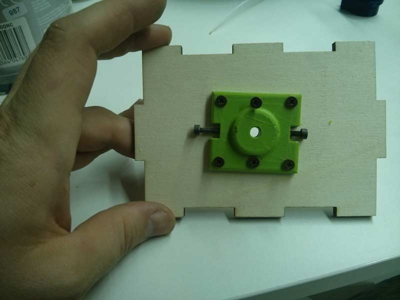
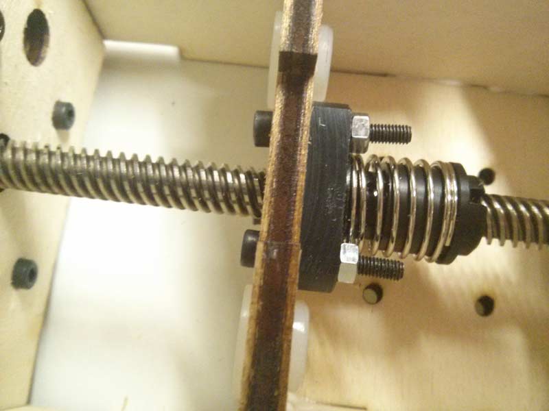
Particular of the 3d printed part, with 6 M8 screws for wood and 2 M3 screws with 2cm nuts.
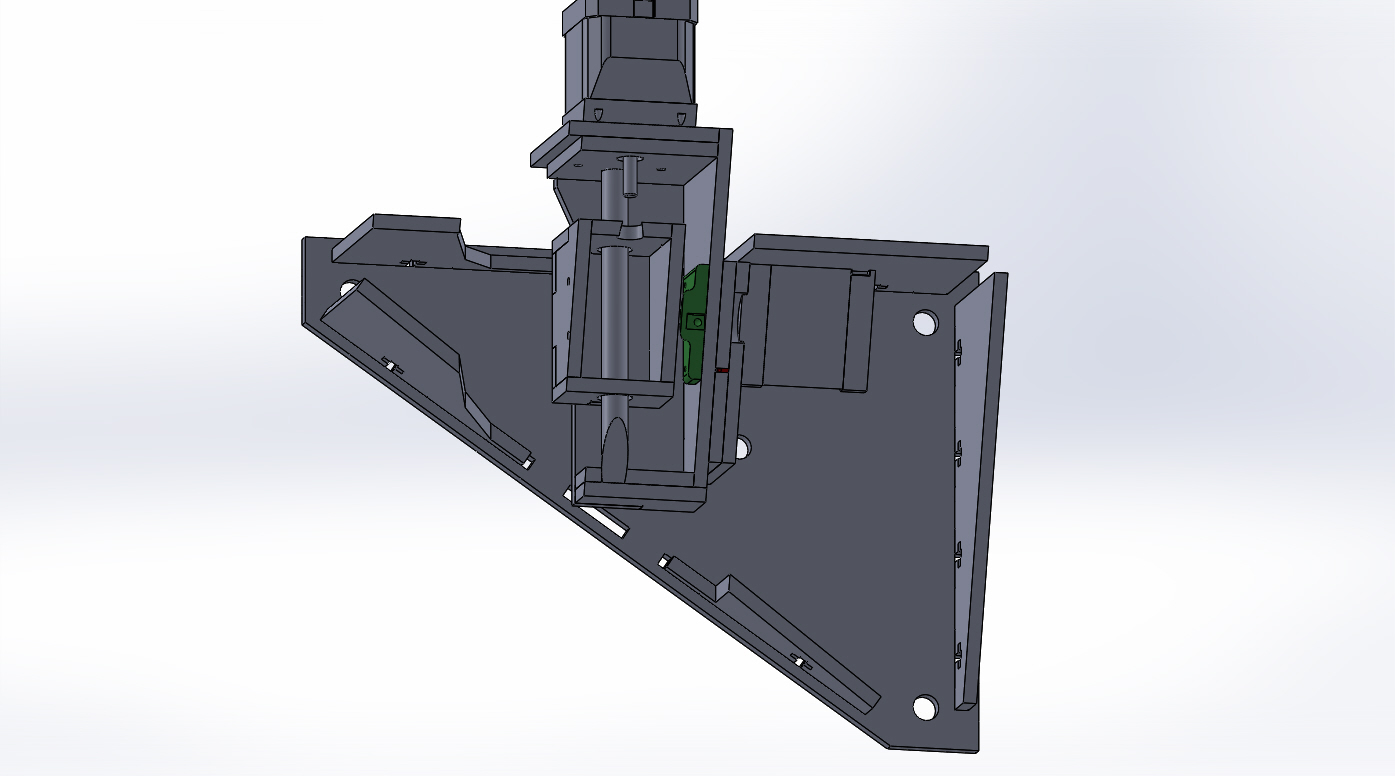
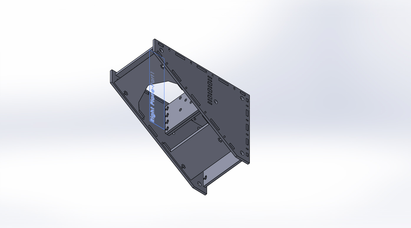
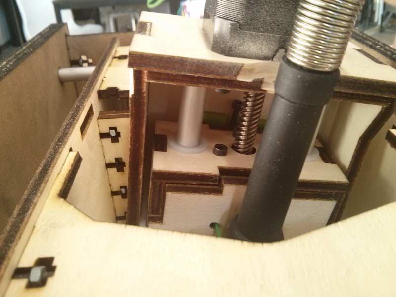
Oblique section of Y & Z & TILT axis
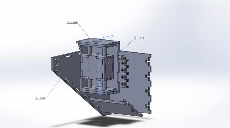
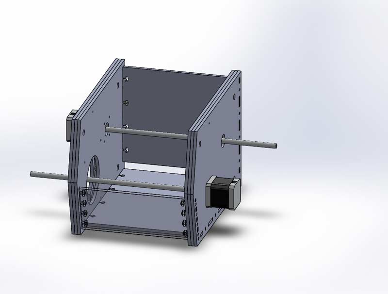
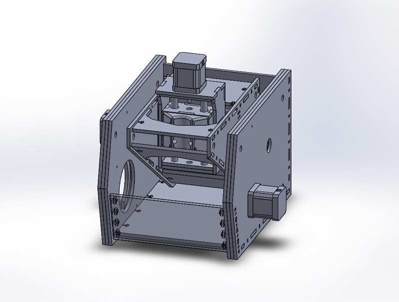
View of Y & Z & TILT axis
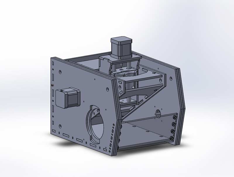
View of Y & Z & TILT axis in rotation
#Assembly
Some pictures of the machine building process.
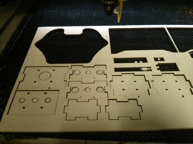
Laser cut at speed 55%, power 100% (material: poplar 5mm)
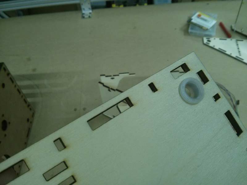
Bearings joint into the 3 apposite holes
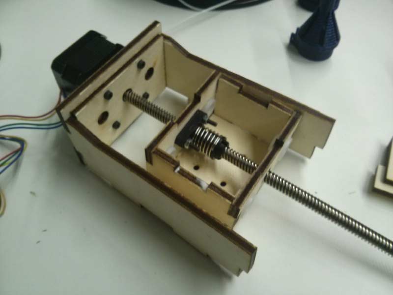
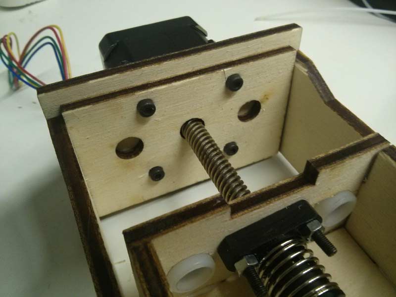
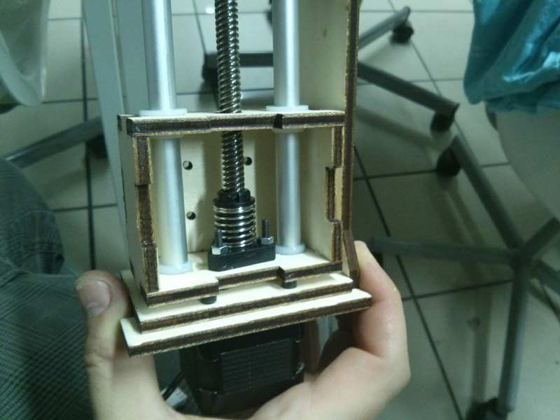
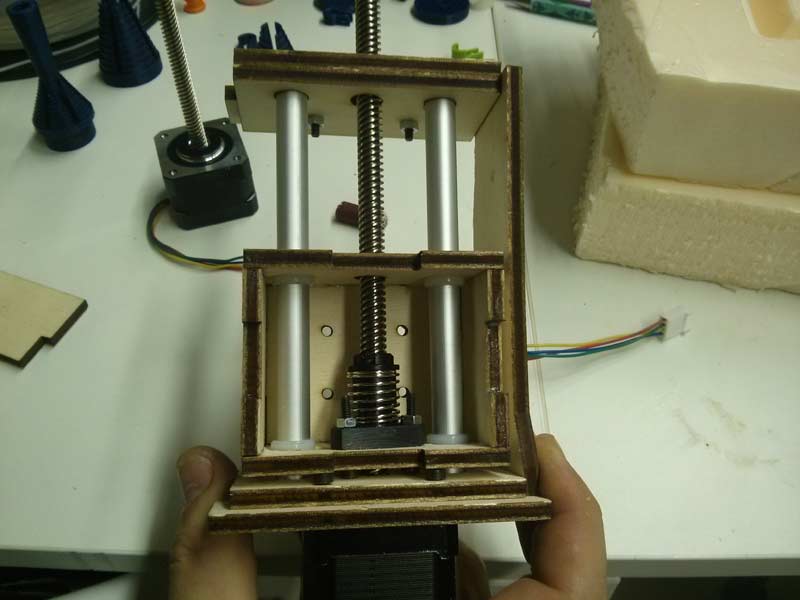
Assembly of the nema 17 on the internal walls of the Y axis, with 4 M3/8mm screws. Joint of the other walls to complete the Y axis.
As you can deduce from the picture, the screws stay inside the apposite holes on the second wall.
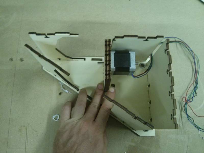
Inserting of the walls with nema 17 inside the Y axis.
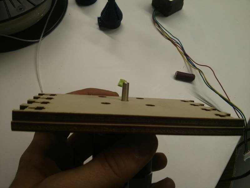
Inserting of 2 M3x20 screws with nuts, to fix the 3d printed element to the nema 17 axle.(tilt)
Getting the Z axis ready with 6 M2 5x8 screws for wood.
Assembling Z axis
Jointing the bearings on the Z axis.
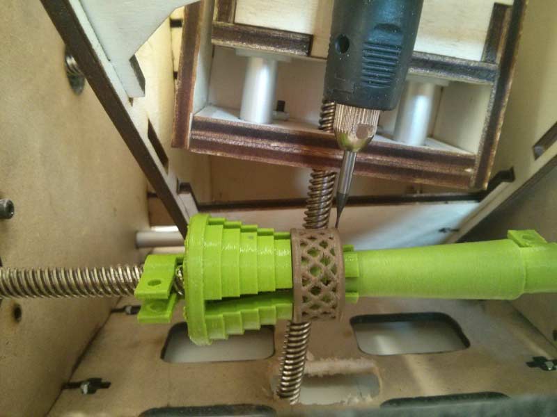
The mandrel is too big! We reshaped it with the dremel, to take off the exceeding part and to manage inserting the mandrel.
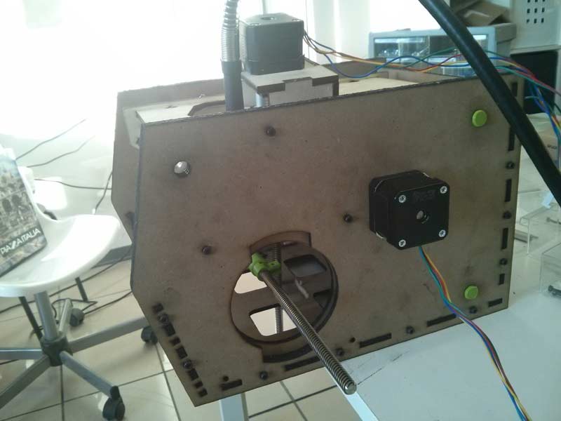
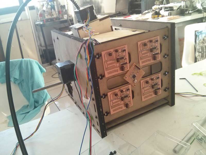
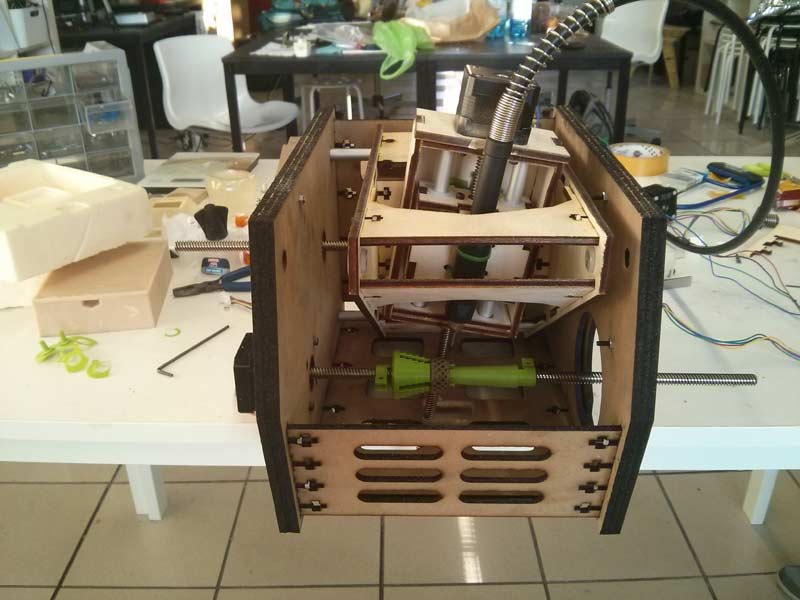
Electronics is temprarly situated on the back.
Testing piece to fix the mandrel to the machine.
#Conclusion
I finally managed to create a completely parametric machine. At the begin of the FabAcademy I was really into doing a final project dedicated to machine, but I preferred facing something completeley unkown (to me). Today, after completing this assignment I am satisfied with this choice, beacuse in this little project I accomplished my wish to design a new machine!
There’s still a lot to be designed, that’s for sure! This is a short list of what that for sure we need to improve for this machine:
- Jointing block on the bearing on the lateral wall
- A smaller mandrel integrated in the Z axis
- Redesign the side walls to allow a wider rotation of the Z axis (TILT)
- Using materials for building better machines
#Source File
Due to large sizes the files are hosted on github. You can find them at github