Weekly_Assignments :
- measure something: add a sensor to a microcontroller board that you've designed and read it
#####Software
- Eletronics Design : Eagle Freeware
- FabModules
#####Useful links:
- HowTo calculate RGB resistor(arduino forum .cc - it)
- touchpad - matt.blackshaw
- multitouch - matthew.keeter
- tinymidi - fiore basile
- led rbg datasheet
#####Materials - Machine
- ######Roland MDX-20
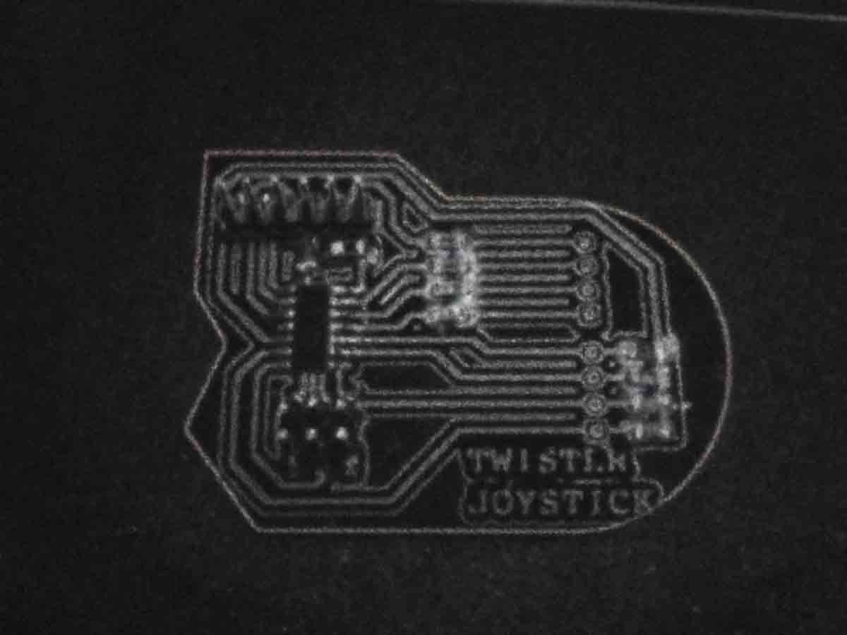
#Twister Joystick two-faced
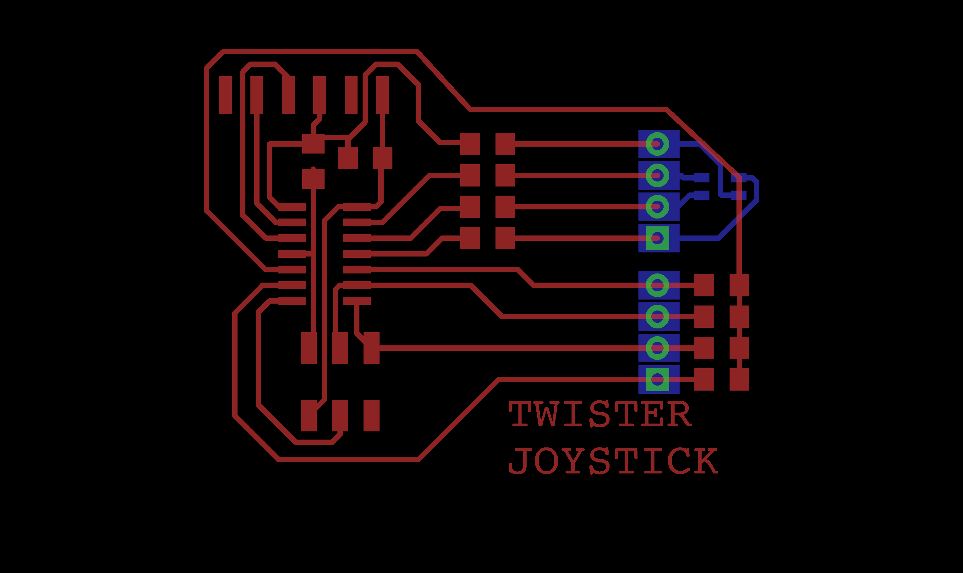
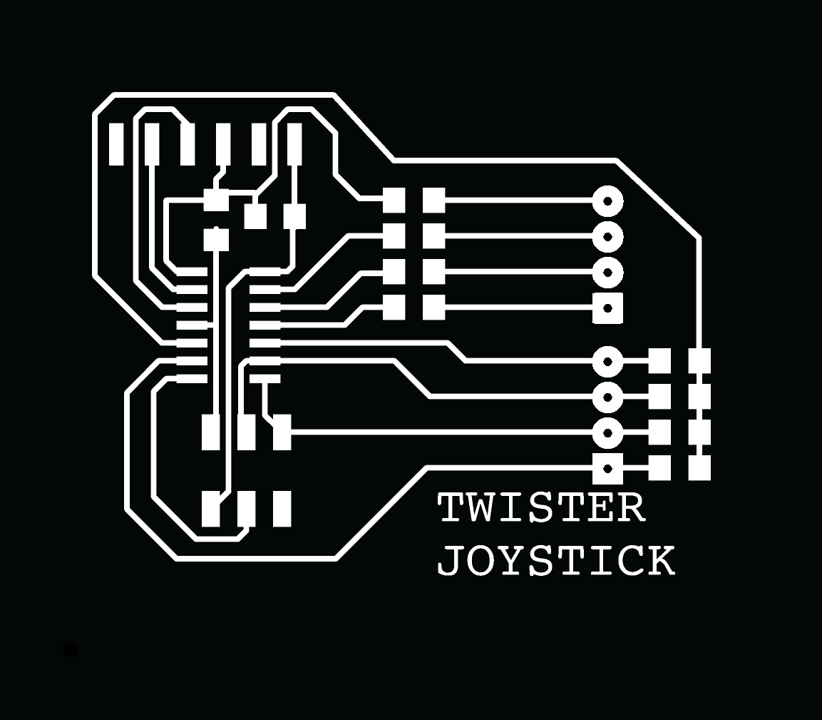
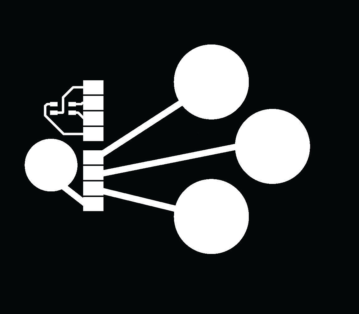
Eagle design
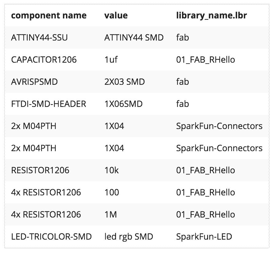
As described in my schedule page for my final project I will need an hardware panel control. I’m really interested into step response projects like touchpad and multitouch. For my joystick (hardware panel control), I only need 4 button (I want it to be sensitive to touch) and one RGB led.
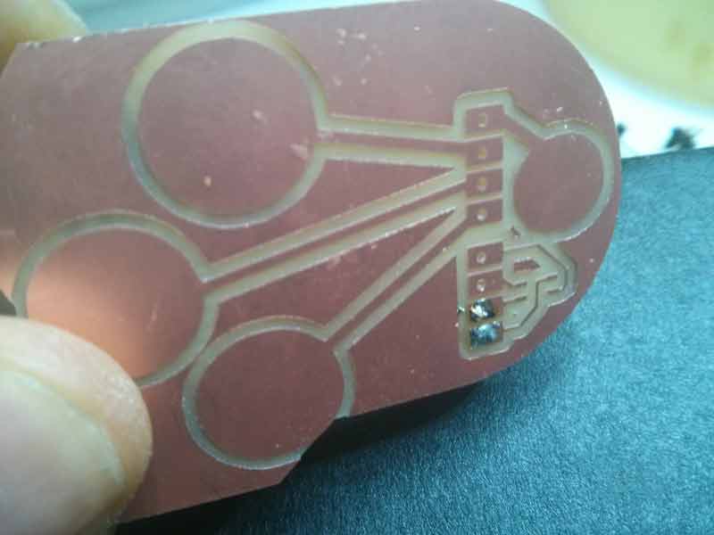
- 2 pads for turning (clockwise and counterclockwise)
- 1 pads for changing cube (switch to another cube)
- 1 pads for changing the color of the cube
- RGB led for visualizing the color cube changing
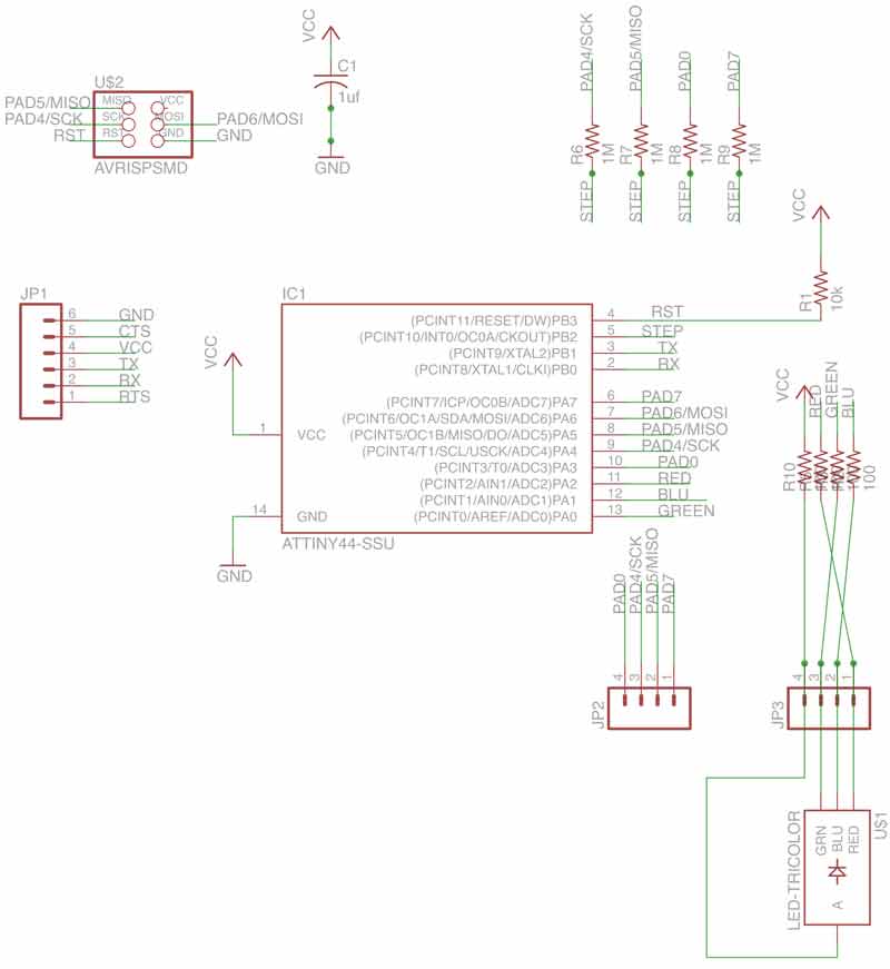
The board has 1M resistor in corrispondence of the step trace, and 3x 100 ohm resistor for RGB led I read the value on datasheet and apply the formula for find the exact color resistor R=(V-Vdrop)/I where:
Example For Red pin (rgb smd led)
- V= 5v
- Vdrop = 2v
- I = 0.02
= 150ohm (in this case in accord with my local istructor I use a 100 ohm resistor)
during the design of the trace I had some problems with avr VCC , so I decided to power my board (also during the programming) with USB-FTDI.
For designing the steps on the back of board in eagle with rgb led and the reference blue-square which correspond to the hole on the front side board. In prevision to import all files in illustrator for designing the step on the back of the board, I designed the square on eagle slightly larger in order to prevent the missing correspondence during the milling.
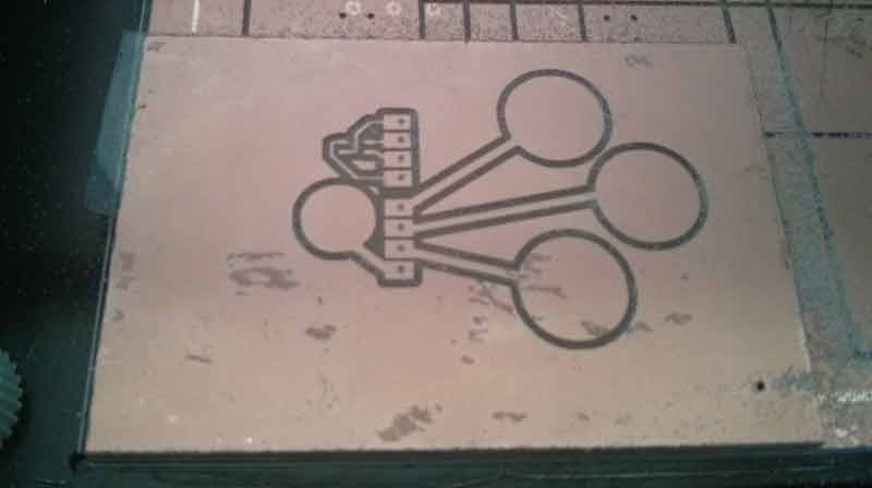
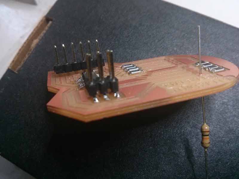
#Milling Board two-faced

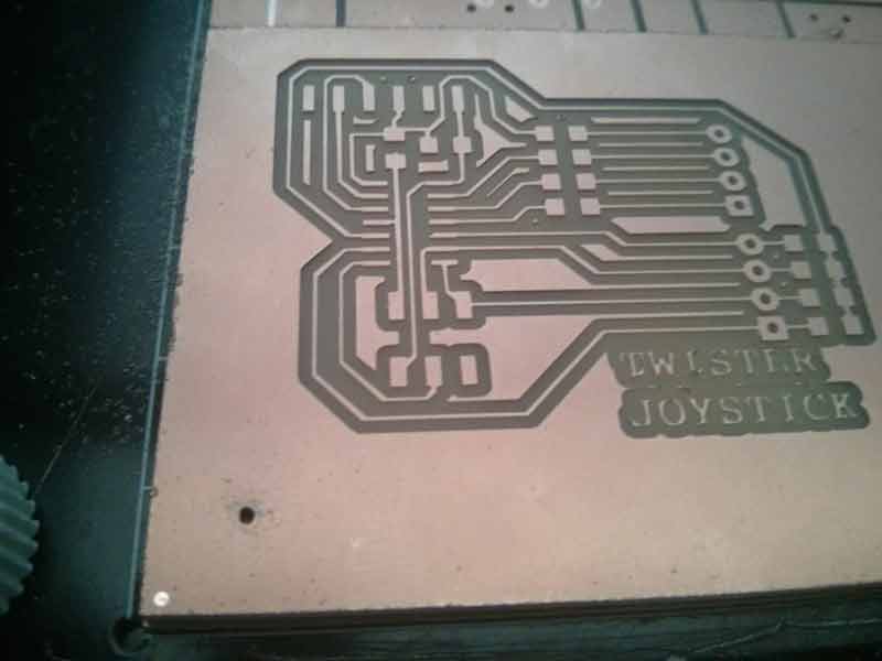
I imported all files in illustrator for designing the distance between the “reference point” and the boarder on holes.png file, needful for milling the back of the board.
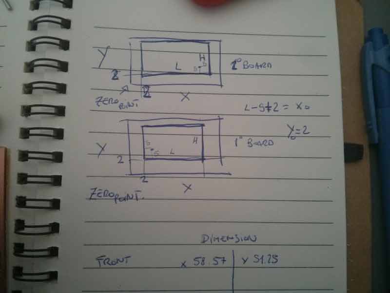
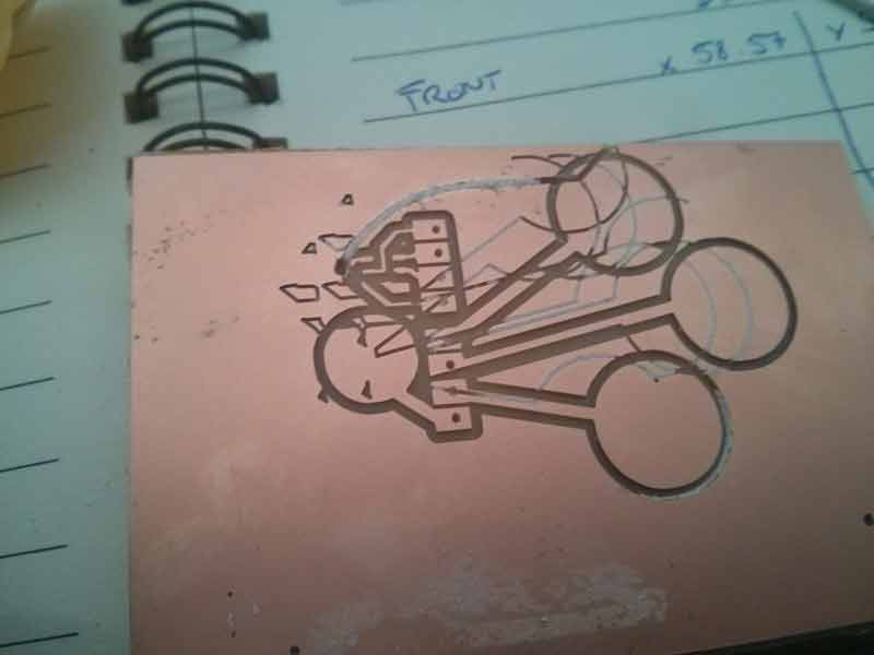
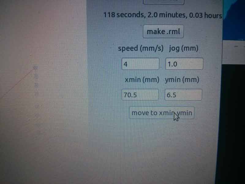
Despite my notes, I didn’t add start-offset, set on the front layer, so I mistaken the first try of my twofaced board…!
Then remenber that back board is mirrored on Y axes and ADD start-offset (adding on the first layer), remember it when you mill the board!
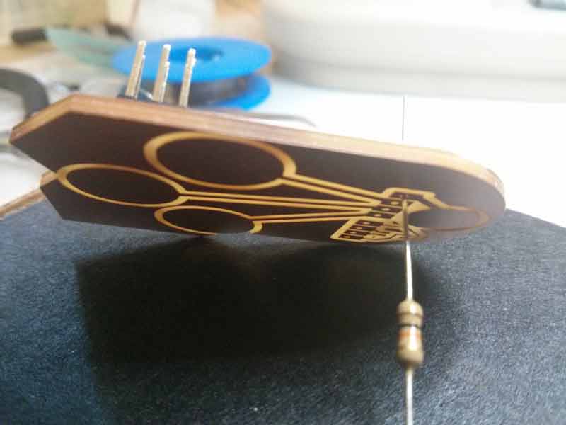
Fiore suggests me to use a resistor wire to solder the passageways from the front to the bottom board, very fast and easy!
#Programming!
I downloaded the code of tinymidi - fiore basileand I modified the code by using my output and input corresponding pin.
After some tests, the threshold values:
| #define down_threshold 700 | –> #define down_threshold 500 |
| #define down_threshold 740 | –> #define up_threshold 550 |
I studied the tinymidi C code, that was perfect for my future application, but I want make a new variant in the future or simply use a neil python for measuring the effective touch sensing.
##Final output result
#Conclusion
I’m really happy at the moment, because for the first time I designed a new one board without anybody’s help, I can understand now something about eletronics, capacitors, resistors , diodes, and also something new about AVR programming!
Due to lack of time, I wasn’t able to develop an interface that would allow me to see moving the twister cube with the variables sent by my joystick via usb-FTDI, but definitely want to do it!
#Source File
##Design Eagle